7059 Manual – P2 – Alemite Strobe Light Wheel Balancer


INTRODUCTION
This manual provides step by step instructions for using the “Alemite” Electronic Wheel Balancer. The wheel balancer is used in detecting and correcting unbalance conditions in rotating wheels. An unbalance condition is corrected by attaching a weight to the truck wheel rim as a counterbalancing force. Through the use of the wheel balancer, the location for attaching the weight and the amount of weight to be attached are determined. For explanation of unbalance conditions, see page 12.
With the electronic balancer, the location and amount of unbalance can be determined without anything being attached to the revolving wheel during balancing procedures.
DESCRIPTION
Your electronic balancer consists of three basic units:
- A wheel spinner which is used only for spinning the front wheels and tandem rear wheels.
- A pick-up unit which is placed under the front suspension or axle to convert the mechanical motion of the suspension into electrical signals and transmit these signals to the meter and strobe light.
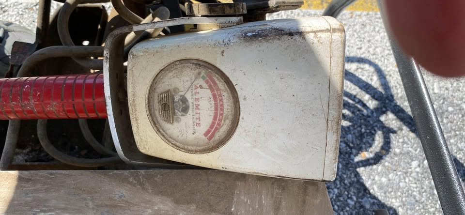
- The portable strobe light which contains a meter to indicate an unbalance condition and a light especially designed for observing objects revolving at high speed. A two position switch on the strobe light controls the sensitivity of the meter. Switch position #1 (Regular) is used throughout the balancing procedure. Switch position #2 (Sensitive) is used only for re-check on critical wheels.
This strobe light will only let you see the position of the wheel when the heavy part is in down position. When the wheel is stopped and rotated to the position shown when using strobe light, the weight should be attached at the top of the wheel.
The instructions are so presented that one front wheel is completely balanced (both kinetically and dynamically) before proceeding to the other front wheel. The rear wheels are balanced kinetically only.
BE SURE TO READ COMPLETE INSTRUCTIONS BEFORE USING BALANCER